Pilot Operated for steam

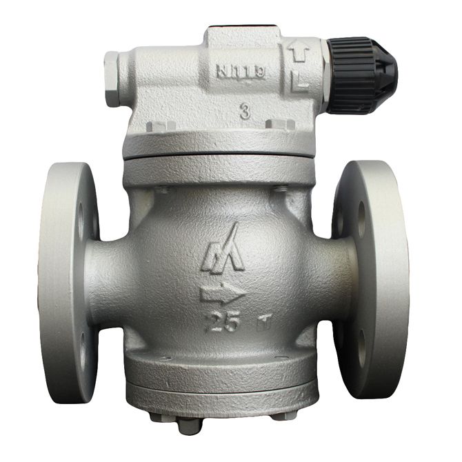
Pressure Reducing Valves Pilot Operated for steam
RE10N
Built-in screen One push blow

Features/Applications
Features
Pressure reducing valves for steam
These are automatic valves that reduce the steam supply pressure to the certified pressure for the device in use, and keep it steady.
Pilot operated valves
The drive section detects the pressure supplied from the pilot chamber, and the degree of opening of the valve is adjusted to keep the pressure on the secondary side at a set level.
Compact and cost effective design
It has a space saving (ultra small/lightweight).
Low heat dissipation with superb energy saving properties and cost performance.Simple pressure adjustment
Pressure adjustment can be performed by hand using a handle, with no tools required. (with lock mechanism)
Superb durability
Offers superb durability thanks to an overstress prevention mechanism.
Easy maintenance
It is easy disassembly and reassembly.
Built-in strainer

Uses
Suitable for a wide range of uses including devices for foodstuffs, dyeing, and cleaning as well as heating equipment and air conditioning equipment.
Dimensions/Weight
Dimensions/Weight

| Size | Dimensions (mm) | Dimensions (in) | Weight | |||||||||
| L | L1 | H1 | H2 | W | L | L1 | H1 | H2 | W | (kg) | (lb) | |
| 1/2” | 160 | 175 | 133 | 80 | 100 | 6.3 | 6.9 | 5.2 | 3.1 | 3.9 | 7,1 | 15.7 |
| 3/4” | 7,4 | 16.3 | ||||||||||
| 1” | 170 | 180 | 6.7 | 7.1 | 8,5 | 18.7 | ||||||
| 1 1/4” | 200 | 210 | 154 | 103 | 130 | 7.9 | 8.3 | 6.1 | 4.1 | 5.1 | 14,2 | 31.3 |
| 1 1/2” | 14,3 | 31.5 | ||||||||||
| 2” | 220 | 220 | 8.7 | 8.7 | 15,6 | 34.4 | ||||||
Specifications
| Model | Connection |
Max. operating pressure |
Operating pressure range |
Control pressure range |
Values |
Max. pressure reduction ratio |
Max. operating temperature |
Body material |
||||||
| Type | Size | (MPa) | (psig) |
Primary side pressure (MPa) |
Primary side pressure (psig) |
Secondary side pressure (MPa) |
Secondary side pressure (psig) |
Cv | Kvs | (℃) | (℉) | |||
| RE10N |
Flanged FF,RF* |
1/2” | 1,6 | 232 | 0,1 - 1,6 | 14.5 - 230 | 0,034 - 1,2 | 4.9 - 174 | 1,0 | 0,9 | 20:1 | 220 | 428 |
Ductile cast iron FCD450 |
| 3/4” | 2,5 | 2,2 | ||||||||||||
| 1” | 4,0 | 3,4 | ||||||||||||
| 1 1/4” | 6,5 | 5,6 | ||||||||||||
| 1 1/2” | 9,0 | 7,7 | ||||||||||||
| 2” | 16,0 | 13,8 | ||||||||||||
● Offset: up to 0,03MPa (4.4psig)
● Minimum differential pressure: 0,07MPa (10.2psig)
● Minimum adjustable flow rate: 5% of the rated flow rate
● Lockup pressure: 0,03MPa (4.4psig) or lower
Capacity Chart

● How to use selection chart (example)
To reduce the pressure of 800kg/h (1764lb/h) of steam from 0,8MPa to 0,5MPa (116psig to 73psig)
1. Find the point at which the primary side pressure 0,8MPa (116psig) curve and secondary side pressure 0,5MPa (73psig) horizontal line intersect.
2. Trace a vertical line from the point where they intersect, and look for the smallest-sized product where the steam flow rate is 800kg/h (1764lb/h) or more at the point where the vertical line you have traced intersects the horizontal size lines.
3. In this case, the pressure reducing valve with a size of 1 1/2” is optimum.
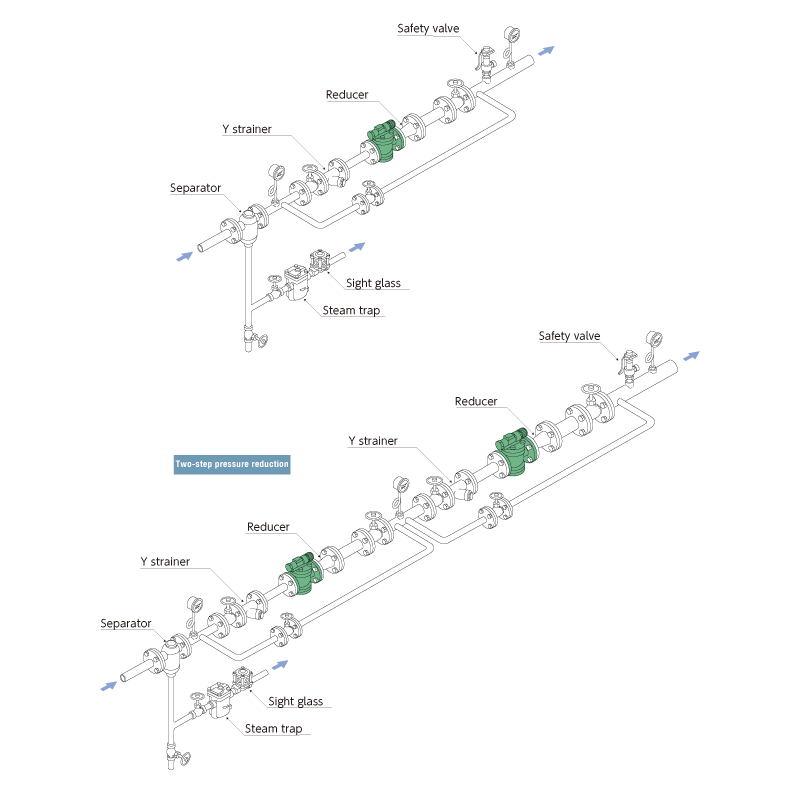
Installation Examples

■Related Products Models for reference
Sight glass TS1 T3 T3
Y strainer YSF
Separator H3 H5
Steam trap Differs depending on conditions
Download
* Membership registration is required to download the documents.
Features
Pressure reducing valves for steam
These are automatic valves that reduce the steam supply pressure to the certified pressure for the device in use, and keep it steady.
Pilot operated valves
The drive section detects the pressure supplied from the pilot chamber, and the degree of opening of the valve is adjusted to keep the pressure on the secondary side at a set level.
Compact and cost effective design
It has a space saving (ultra small/lightweight).
Low heat dissipation with superb energy saving properties and cost performance.Simple pressure adjustment
Pressure adjustment can be performed by hand using a handle, with no tools required. (with lock mechanism)
Superb durability
Offers superb durability thanks to an overstress prevention mechanism.
Easy maintenance
It is easy disassembly and reassembly.
Built-in strainer

Uses
Suitable for a wide range of uses including devices for foodstuffs, dyeing, and cleaning as well as heating equipment and air conditioning equipment.
Dimensions/Weight

| Size | Dimensions (mm) | Dimensions (in) | Weight | |||||||||
| L | L1 | H1 | H2 | W | L | L1 | H1 | H2 | W | (kg) | (lb) | |
| 1/2” | 160 | 175 | 133 | 80 | 100 | 6.3 | 6.9 | 5.2 | 3.1 | 3.9 | 7,1 | 15.7 |
| 3/4” | 7,4 | 16.3 | ||||||||||
| 1” | 170 | 180 | 6.7 | 7.1 | 8,5 | 18.7 | ||||||
| 1 1/4” | 200 | 210 | 154 | 103 | 130 | 7.9 | 8.3 | 6.1 | 4.1 | 5.1 | 14,2 | 31.3 |
| 1 1/2” | 14,3 | 31.5 | ||||||||||
| 2” | 220 | 220 | 8.7 | 8.7 | 15,6 | 34.4 | ||||||
| Model | Connection |
Max. operating pressure |
Operating pressure range |
Control pressure range |
Values |
Max. pressure reduction ratio |
Max. operating temperature |
Body material |
||||||
| Type | Size | (MPa) | (psig) |
Primary side pressure (MPa) |
Primary side pressure (psig) |
Secondary side pressure (MPa) |
Secondary side pressure (psig) |
Cv | Kvs | (℃) | (℉) | |||
| RE10N |
Flanged FF,RF* |
1/2” | 1,6 | 232 | 0,1 - 1,6 | 14.5 - 230 | 0,034 - 1,2 | 4.9 - 174 | 1,0 | 0,9 | 20:1 | 220 | 428 |
Ductile cast iron FCD450 |
| 3/4” | 2,5 | 2,2 | ||||||||||||
| 1” | 4,0 | 3,4 | ||||||||||||
| 1 1/4” | 6,5 | 5,6 | ||||||||||||
| 1 1/2” | 9,0 | 7,7 | ||||||||||||
| 2” | 16,0 | 13,8 | ||||||||||||
● Offset: up to 0,03MPa (4.4psig)
● Minimum differential pressure: 0,07MPa (10.2psig)
● Minimum adjustable flow rate: 5% of the rated flow rate
● Lockup pressure: 0,03MPa (4.4psig) or lower

● How to use selection chart (example)
To reduce the pressure of 800kg/h (1764lb/h) of steam from 0,8MPa to 0,5MPa (116psig to 73psig)
1. Find the point at which the primary side pressure 0,8MPa (116psig) curve and secondary side pressure 0,5MPa (73psig) horizontal line intersect.
2. Trace a vertical line from the point where they intersect, and look for the smallest-sized product where the steam flow rate is 800kg/h (1764lb/h) or more at the point where the vertical line you have traced intersects the horizontal size lines.
3. In this case, the pressure reducing valve with a size of 1 1/2” is optimum.

■Related Products Models for reference
Sight glass TS1 T3 T3
Y strainer YSF
Separator H3 H5
Steam trap Differs depending on conditions
* Membership registration is required to download the documents.