Air Vents for Steam
Air Vents Air Vents for Steam
AT51
Features/Applications
Features
Quick startup
Swiftly discharges the initial cold condensate and air.
Superb durability
The MIYAWAKI SCCV (Self Closing and Centering Valve) System has the effect of increasing durability by achieving soft closing during operation. Consisting of a free rotating valve that is centered and guided by the condensate flow, hence perfectly fitted in the valve seat even under extreme conditions of high pressure applications. This significantly reduces wear and erosion of the valve components.
Accurate operation in high pressure and high temperature ranges, and in the presence of superheated steam.
Easy maintenance
Internal components being grouped into units make it maintenance easy.
Typical applications
Suitable for steam main lines, trace lines, and other such applications.
Dimensions/Weight
Dimensions/Weight
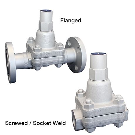
Screwed / Socket Weld

| Size | Dimensions (mm) | Dimensions (in) | Weight | |||||||
| L | H1 | H2 | W | L | H1 | H2 | W | (kg) | (lb) | |
| 1/2” | 130 | 155 | 25 | 100 | 5.1 | 6.1 | 1.0 | 3.9 |
5,7 |
12.6 |
| 3/4” | ||||||||||
| 1” | ||||||||||
Flanged

| Size | Flange standards | Dimensions (mm) | Dimensions (in) | Weight | ||||||||
| L | H1 | H2 | W | L | H1 | H2 | W | (kg) | (lb) | |||
| 1/2” | JIS (RF) |
20K |
200 |
155 | 25 | 100 | 7.9 | 6.1 | 1.0 | 3.9 |
7,3 |
16.1 |
| 30K | 8,4 | 18.5 | ||||||||||
| 40K | 8,7 | 19.2 | ||||||||||
| 63K | 220 | 8.7 | 9,6 | 21.2 | ||||||||
| ASME/JPI (RF) |
150lb | 200 | 7.9 | 6,7 | 14.8 | |||||||
| 300lb | 7,2 | 15.9 | ||||||||||
| 600lb | 7,3 | 16.1 | ||||||||||
| 900lb | 220 | 8.7 | 9,6 | 21.2 | ||||||||
| 3/4” | JIS (RF) |
20K | 210 | 8.3 | 7,7 | 17.0 | ||||||
| 30K | 8,9 | 19.6 | ||||||||||
| 40K | 9,2 | 20.3 | ||||||||||
| 63K | 230 | 9.1 | 11,1 | 24.5 | ||||||||
| ASME/JPI (RF) |
150lb | 210 | 8.3 | 7,7 | 17.0 | |||||||
| 300lb | 8,2 | 18.1 | ||||||||||
| 600lb | 8,5 | 18.7 | ||||||||||
| 900lb | 230 | 9.1 | 10,9 | 24.0 | ||||||||
| 1” | JIS (RF) |
20K | 240 | 9.5 | 9,2 | 20.3 | ||||||
| 30K | 10,1 | 22.3 | ||||||||||
| 40K | 10,5 | 23.2 | ||||||||||
| 63K | 12,1 | 26.7 | ||||||||||
| ASME/JPI (RF) |
150lb | 8,3 | 18.3 | |||||||||
| 300lb | 9,4 | 20.7 | ||||||||||
| 600lb | 9,6 | 21.2 | ||||||||||
| 900lb | 13,3 | 29.3 | ||||||||||
| Size | Flange standards | Dimensions (mm) | Dimensions (in) | Weight | ||||||||
| L | H1 | H2 | W | L | H1 | H2 | W | (kg) | (lb) | |||
| DN15 | DIN PN63/PN100 | 210 | 155 | 25 | 100 | 8.3 | 6.1 | 1.0 | 3.9 | 9,4 | 20.7 | |
| DN20 | 230 | 9.1 | 11,4 | 25.1 | ||||||||
| DN25 | 12,1 | 26.7 | ||||||||||
*Manufacturing with custom face-to-face dimensions for flanged connection is also possible.
*Please do not hesitate to inquire about the face-to-face dimensions that can be manufactured.
Specifications
| Model | Connection |
Max. operating pressure |
Max. operating pressure differential |
Max. operating temperature |
Controlled temperature range |
Standard set temperature |
Body material |
||||||
| Type | Size | (MPa) | (psig) | (MPa) | (psig) |
TMO (℃) |
TMO (℉) |
(℃) | (℉) | (℃) | (℉) | ||
| TB51-45 |
Screwed Rc,NPT |
1/2” |
4,5 |
652.5 | 4,5 | 652.5 | 425 | 797 | 100 - 220 | 212 - 428 |
180 (at 2,1MPa) |
356 (at 304.5psig) |
Forged steel A105 |
| 3/4” | |||||||||||||
| 1” | |||||||||||||
| TB51-65 | 1/2” | 6,5 | 942.5 | 6,5 | 942.5 | 100 - 240 | 212 - 464 |
220 (at 4,4MPa) |
428 (at 638psig) |
||||
| 3/4” | |||||||||||||
| 1” | |||||||||||||
| TB51F-45 |
Flanged RF
|
1/2” | 4,5 | 652.5 | 4,5 | 652.5 | 100 - 220 | 212 - 428 |
180 (at 2,1MPa) |
356 (at 304.5psig) |
|||
| 3/4” | |||||||||||||
| 1” | |||||||||||||
| TB51F-65 | 1/2” | 6,5 | 942.5 | 6,5 | 942.5 | 100 - 240 | 212 - 464 |
220 (at 4,4MPa) |
428 (at 638psig) |
||||
| 3/4” | |||||||||||||
| 1” | |||||||||||||
| TB51W-45 |
Socket Weld SW
|
1/2” | 4,5 | 652.5 | 4,5 | 652.5 | 100 - 220 | 212 - 428 |
180 (at 2,1MPa) |
356 (at 304.5psig) |
|||
| 3/4” | |||||||||||||
| 1” | |||||||||||||
| TB51W-65 | 1/2” | 6,5 | 942.5 | 6,5 | 942.5 | 100 - 240 | 212 - 464 |
220 (at 4,4MPa) |
428 (at 638psig) |
||||
| 3/4” | |||||||||||||
| 1” | |||||||||||||
*It is possible to change the factory default set temperature. Specify the operating pressure and set temperature.
Download
* Membership registration is required to download the documents.
Features
Quick startup
Swiftly discharges the initial cold condensate and air.
Superb durability
The MIYAWAKI SCCV (Self Closing and Centering Valve) System has the effect of increasing durability by achieving soft closing during operation. Consisting of a free rotating valve that is centered and guided by the condensate flow, hence perfectly fitted in the valve seat even under extreme conditions of high pressure applications. This significantly reduces wear and erosion of the valve components.
Accurate operation in high pressure and high temperature ranges, and in the presence of superheated steam.
Easy maintenance
Internal components being grouped into units make it maintenance easy.
Typical applications
Suitable for steam main lines, trace lines, and other such applications.
Dimensions/Weight
Screwed / Socket Weld
| Size | Dimensions (mm) | Dimensions (in) | Weight | |||||||
| L | H1 | H2 | W | L | H1 | H2 | W | (kg) | (lb) | |
| 1/2” | 130 | 155 | 25 | 100 | 5.1 | 6.1 | 1.0 | 3.9 |
5,7 |
12.6 |
| 3/4” | ||||||||||
| 1” | ||||||||||
Flanged
| Size | Flange standards | Dimensions (mm) | Dimensions (in) | Weight | ||||||||
| L | H1 | H2 | W | L | H1 | H2 | W | (kg) | (lb) | |||
| 1/2” | JIS (RF) |
20K |
200 |
155 | 25 | 100 | 7.9 | 6.1 | 1.0 | 3.9 |
7,3 |
16.1 |
| 30K | 8,4 | 18.5 | ||||||||||
| 40K | 8,7 | 19.2 | ||||||||||
| 63K | 220 | 8.7 | 9,6 | 21.2 | ||||||||
| ASME/JPI (RF) |
150lb | 200 | 7.9 | 6,7 | 14.8 | |||||||
| 300lb | 7,2 | 15.9 | ||||||||||
| 600lb | 7,3 | 16.1 | ||||||||||
| 900lb | 220 | 8.7 | 9,6 | 21.2 | ||||||||
| 3/4” | JIS (RF) |
20K | 210 | 8.3 | 7,7 | 17.0 | ||||||
| 30K | 8,9 | 19.6 | ||||||||||
| 40K | 9,2 | 20.3 | ||||||||||
| 63K | 230 | 9.1 | 11,1 | 24.5 | ||||||||
| ASME/JPI (RF) |
150lb | 210 | 8.3 | 7,7 | 17.0 | |||||||
| 300lb | 8,2 | 18.1 | ||||||||||
| 600lb | 8,5 | 18.7 | ||||||||||
| 900lb | 230 | 9.1 | 10,9 | 24.0 | ||||||||
| 1” | JIS (RF) |
20K | 240 | 9.5 | 9,2 | 20.3 | ||||||
| 30K | 10,1 | 22.3 | ||||||||||
| 40K | 10,5 | 23.2 | ||||||||||
| 63K | 12,1 | 26.7 | ||||||||||
| ASME/JPI (RF) |
150lb | 8,3 | 18.3 | |||||||||
| 300lb | 9,4 | 20.7 | ||||||||||
| 600lb | 9,6 | 21.2 | ||||||||||
| 900lb | 13,3 | 29.3 | ||||||||||
| Size | Flange standards | Dimensions (mm) | Dimensions (in) | Weight | ||||||||
| L | H1 | H2 | W | L | H1 | H2 | W | (kg) | (lb) | |||
| DN15 | DIN PN63/PN100 | 210 | 155 | 25 | 100 | 8.3 | 6.1 | 1.0 | 3.9 | 9,4 | 20.7 | |
| DN20 | 230 | 9.1 | 11,4 | 25.1 | ||||||||
| DN25 | 12,1 | 26.7 | ||||||||||
*Manufacturing with custom face-to-face dimensions for flanged connection is also possible.
*Please do not hesitate to inquire about the face-to-face dimensions that can be manufactured.
| Model | Connection |
Max. operating pressure |
Max. operating pressure differential |
Max. operating temperature |
Controlled temperature range |
Standard set temperature |
Body material |
||||||
| Type | Size | (MPa) | (psig) | (MPa) | (psig) |
TMO (℃) |
TMO (℉) |
(℃) | (℉) | (℃) | (℉) | ||
| TB51-45 |
Screwed Rc,NPT |
1/2” |
4,5 |
652.5 | 4,5 | 652.5 | 425 | 797 | 100 - 220 | 212 - 428 |
180 (at 2,1MPa) |
356 (at 304.5psig) |
Forged steel A105 |
| 3/4” | |||||||||||||
| 1” | |||||||||||||
| TB51-65 | 1/2” | 6,5 | 942.5 | 6,5 | 942.5 | 100 - 240 | 212 - 464 |
220 (at 4,4MPa) |
428 (at 638psig) |
||||
| 3/4” | |||||||||||||
| 1” | |||||||||||||
| TB51F-45 |
Flanged RF
|
1/2” | 4,5 | 652.5 | 4,5 | 652.5 | 100 - 220 | 212 - 428 |
180 (at 2,1MPa) |
356 (at 304.5psig) |
|||
| 3/4” | |||||||||||||
| 1” | |||||||||||||
| TB51F-65 | 1/2” | 6,5 | 942.5 | 6,5 | 942.5 | 100 - 240 | 212 - 464 |
220 (at 4,4MPa) |
428 (at 638psig) |
||||
| 3/4” | |||||||||||||
| 1” | |||||||||||||
| TB51W-45 |
Socket Weld SW
|
1/2” | 4,5 | 652.5 | 4,5 | 652.5 | 100 - 220 | 212 - 428 |
180 (at 2,1MPa) |
356 (at 304.5psig) |
|||
| 3/4” | |||||||||||||
| 1” | |||||||||||||
| TB51W-65 | 1/2” | 6,5 | 942.5 | 6,5 | 942.5 | 100 - 240 | 212 - 464 |
220 (at 4,4MPa) |
428 (at 638psig) |
||||
| 3/4” | |||||||||||||
| 1” | |||||||||||||
*It is possible to change the factory default set temperature. Specify the operating pressure and set temperature.
* Membership registration is required to download the documents.